
Beginner’s Guide to the 12V Time Delay Relay Module
Whether you're building a DIY automation system or just experimenting with electronics, the 12V Time Delay Relay Module (SRD-12VDC-SL-C) is a super handy device. In this post, We’ll explain how it works and walk you through an example to get started.
This module allows you to delay the activation of a connected device (like a light, fan, or pump) after power is applied or a trigger is received. It’s perfect for automating tasks with a built-in adjustable delay.
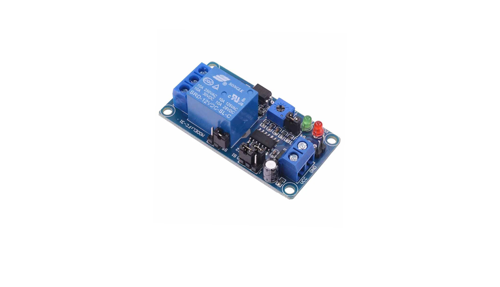
🔌 Pin & Terminal Overview
The diagram show the pins and terminals for the time delay module. The module is also available for 5VDC. Time adjustable potentiometer and time range selection headers for 0.1 seconds to 1 hour delay.

Power Pins:
-
VCC – Connect to +12V DC
-
GND – Connect to ground of power supply
Relay Output Terminals:
-
COM (Common) – Shared line between NC and NO
-
NO (Normally Open) – Will open the circuit after the delay (turn an LED off for example)
-
NC (Normally Closed) – Will close the circuit after the delay (turn an LED on for example)
Timing Jumpers:
-
S1 and S2 – Select the timing range (table below)
-
S4 – Optional: doubles the delay range when jumper is added
Other:
-
Timing adjustment– Blue potentiometer to fine-tune delay within selected range
-
PWR LED (Red) – Power indicator
-
TIME LED (Green) – Lights up when relay is active
Delay Time Settings
You set the time delay using jumper caps across S1, S2, and optionally S4. The table below shows the available time delays and the required settings. You can move the jumper headers to the appropriate position for the time delay required.

0: leave empty 1: Close/Plug

S1 and S2 header combinations, adjust to match the table above to set your required time delay.
💡 Test Project: Lighting an LED with Delay
Here’s how to wire a basic LED that turns on after a delay using this module.
🔧 What You Need:
-
12V battery or power adapter
-
12V relay module
-
Closed link headers for the switch, or a pushbutton
🔌 Wiring Instructions:
The diagram below shows a simple set up to wire an LED to the relay board. Best to use a prewired 12V LED so you don't need to solder in a resistor yourself!

-
Power the Module:
-
VCC → +12V
-
GND → Battery ground -12V
-
Red LED should turn on (PWR)
-
-
Set Timing:
-
S1 = 0, S2 = 1, S4 = open → ~1-second delay
-
Adjust potentiometer for fine control
-
-
Relay Output Wiring:
-
+12V (from battery) → COM terminal
-
NO terminal → + of LED
-
– (cathode) → - of LED
-
-
Trigger the Relay:
-
Activate the relay with the switch pins - you can used a closed header (jumper cap) to connect these so the relay is activated or solder in a pushbutton switch.
-
After delay, green LED turns on and relay clicks (you will hear the click)
-
LED lights up!
-
✅ Tips & Safety
-
Always test with low-voltage loads first (like an LED).
-
If using AC devices, ensure proper insulation and relay rating (10A max).
-
You can use this module to control fans, buzzers, lamps, or even small motors
Final Thoughts
This relay module is a simple but powerful addition to any electronics or automation project. Once you get the hang of setting the time ranges and wiring the outputs correctly, it is a really useful bit of kit!
Comments
Leave a comment